
It started of with my SD-WAN lab. After hours of studying and eventually adding a few vEdges to finalize the Control Plane bringup, I was ready for templating, creating different BFD topologies and all the fun SD-WAN provides.
But I just had one single WAN link from my DC all the way to the branch office. The whole WAN was just two routers and one link. Obviously this would work fine configuring the vEdge device and testing a few features, but it just wasn’t the real deal.
Let’s build a real MPLS WAN transport. Then we can also play around with increased jitter and packet loss within the WAN transport and see how my defined SLA responds to that. I might learn some new tricks in MPLS and MP-BGP.
:: Some basics
Before we start configuring some routers like a wild man, lets first define what we need and how to built it. From my experience I know that we can split MPLS into two types:
- MPLS L2 VPN
- MPLS L3 VPN
To make sure I can expand the topology and play around with “customers” and different transport paths for my SD-WAN lab I’ve chosen MPLS L3VPN. Not the easiest of the two.
The transport medium will contain the following separated functions:
:: CE Nodes
Customer Edge nodes, CE nodes provide a means to interconnect a site to the MPLS network. It doesn’t have to be VRF aware. It can be static, but I will use OSPF as the routing protocol towards the PE routers.
:: PE Nodes
Provider Edge nodes, this is where the encapsulation into MPLS happens and the VPN id are transported as an extra label over the transport. They also need to be VRF aware in order to extend the VPN across the MPLS network. Packets get a label (and VPN label) assigned to be forwarded over the P-network. We also use BGP extension to import and export VPN’s according to a defined Route Distinguisher and thus allowing sites or customer to ” talk” to each other or not.
:: P Nodes
Provider Core nodes make up the MPLS transport network and make forwarding decisions based on labels. You should run a routing protocol to create reachability in the P-Network. For large scaled network IS-IS would be the preferred choice. In my case I will use OSPF.
:: Topology
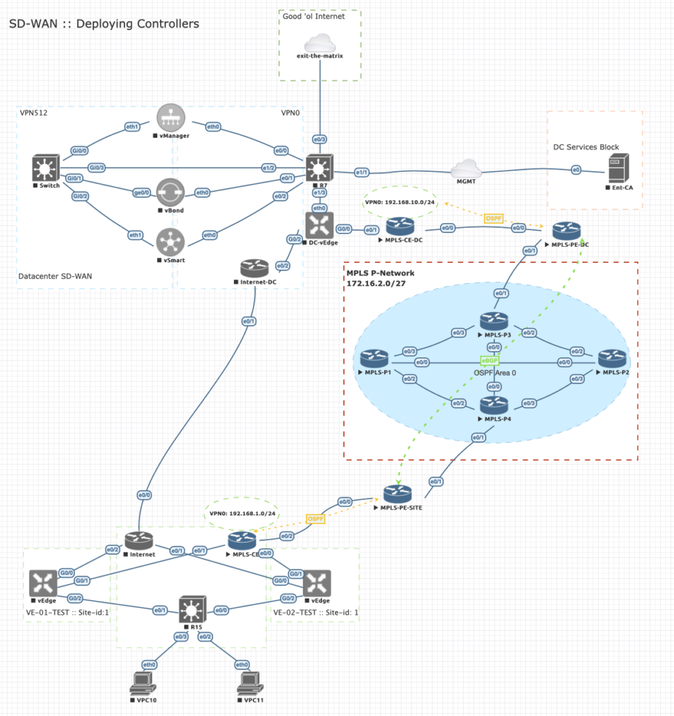
Below is the full SD-WAN lab. All nodes in blue will be the scope of our topology:
:: Approach
On both the CE routers I’ve installed Loopback9000 to advertise a test network prefix into the VPN and be transported across the MPLS P-network. After configuring the topology these two prefixes should be able to talk to each other.
I’ve created a small IP plan before configuring to make sure we don’t end up with silly IP connectivity issues:
| Router | Interface | IP Range | Interface | Router | IP Validation |
| MPLS-PE-DC | e0/0 | 172.18.10.0/24 | e0/0 | MPLS-CE-DC | OK |
| MPLS-PE-DC | e0/1 | 172.16.2.24/30 | e0/1 | MPLS-P3 | OK |
| MPLS-PE-SITE | e0/0 | 172.18.20.0/24 | e0/2 | MPLS-CE-SITE | OK |
| MPLS-PE-SITE | e0/1 | 172.16.2.28/30 | e0/1 | MPLS-P4 | OK |
| MPLS-P3 | e0/0 | 172.16.2.0/30 | e0/0 | MPLS-P4 | OK |
| MPLS-P3 | e0/3 | 172.16.2.8/30 | e0/3 | MPLS-P1 | OK |
| MPLS-P4 | e0/2 | 172.16.2.12/30 | e0/2 | MPLS-P1 | OK |
| MPLS-P4 | e0/3 | 172.16.2.16/30 | e0/3 | MPLS-P2 | OK |
| MPLS-P2 | e0/0 | 172.16.2.20/30 | e0/0 | MPLS-P1 | OK |
| MPLS-P2 | e0/2 | 172.16.2.4/30 | e0/2 | MPLS-P3 | OK |
The P-network will carry IP range 172.16.2.0/27 (8 p2p links). The PE to CE transports will be IP ranges 172.18.10.0/24 and 172.18.20.0/24
When doing a traceroute you can clearly identify CE-PE and P communications.
I’m not going into details about how to configure the p2p links. This should be a “no-brainer” when playing around with MPLS. Below a small list what to do in to create the base configuration:
- Base configuration with ‘IP cef’ and ‘no ip domain-lookup’ 🙂
- Configure p2p links P-nodes
- Configure Loopback interface P-nodes
- Configure p2p links P-PE nodes
- Configure Loopback interfaces PE-nodes
- Configure p2p link CE-PE nodes
- Configure Loopback interfaces CE-nodes
- Check p2p IP connectivity
| Node | Function |
| MPLS-CE-DC | OSPF handover to PE |
| MPLS-PE-DC | OSPF/MPLS and MP-BGP |
| MPLS-CE-SITE | OSPF handover to PE |
| MPLS-PE-SITE | OSPF/MPLS and MP-BGP |
| MPLS-P1 | MPLS (LDP) |
| MPLS-P2 | MPLS (LDP) |
| MPLS-P3 | MPLS (LDP) |
| MPLS-P4 | MPLS (LDP) |
:: Configure P-Network for MPLS and reachability with OSPF
Configurations on all P-nodes:
!
! >> 'MPLS IP' is turned on by default, but for sake of clarity included
mpls ip
mpls label protocol ldp
!
Interface range ethx/x
 mpls label protocol ldp
 mpls ip
!
! >> Force to use loopback in MPLS
mpls ldp router-id Loopback{#} force
!
!
router ospf 1
! >> Always advertise loopback interfaces for reachability
 network {loopback-address} 0.0.0.0 area 0
!
! >> Advertise P-network subnets
 network 172.16.2.0 0.0.0.31 area 0
!
Result:
Soon after configuring you will notice some notifications pop up:
<omitted>
*Jun 20 09:59:59.443: %SYS-5-CONFIG_I: Configured from console by console
*Jun 20 10:01:00.688: %OSPF-5-ADJCHG: Process 1, Nbr 4.4.4.4 on Ethernet0/0 from LOADING to FULL, Loading Done
*Jun 20 10:01:05.739: %LDP-5-NBRCHG: LDP Neighbor 4.4.4.4:0 (1) is UP
*Jun 20 10:02:54.921: %OSPF-5-ADJCHG: Process 1, Nbr 2.2.2.2 on Ethernet0/2 from LOADING to FULL, Loading Done
*Jun 20 10:03:00.442: %LDP-5-NBRCHG: LDP Neighbor 2.2.2.2:0 (2) is UP
*Jun 20 10:03:14.586: %OSPF-5-ADJCHG: Process 1, Nbr 1.1.1.1 on Ethernet0/3 from LOADING to FULL, Loading Done
*Jun 20 10:03:20.111: %LDP-5-NBRCHG: LDP Neighbor 1.1.1.1:0 (3) is UP
Output:
======================================================================
MPLS-P3#show mpls ldp neighbor
    Peer LDP Ident: 4.4.4.4:0; Local LDP Ident 3.3.3.3:0
TCP connection: 4.4.4.4.33304 - 3.3.3.3.646
State: Oper; Msgs sent/rcvd: 18/18; Downstream
Up time: 00:02:56
LDP discovery sources:
  Ethernet0/0, Src IP addr: 172.16.2.2
        Addresses bound to peer LDP Ident:
          172.16.2.2      172.16.2.30     172.16.2.14     172.16.2.17
          4.4.4.4
    Peer LDP Ident: 2.2.2.2:0; Local LDP Ident 3.3.3.3:0
TCP connection: 2.2.2.2.646 - 3.3.3.3.49129
State: Oper; Msgs sent/rcvd: 16/16; Downstream
Up time: 00:01:02
LDP discovery sources:
  Ethernet0/2, Src IP addr: 172.16.2.6
        Addresses bound to peer LDP Ident:
          172.16.2.21     172.16.2.6      172.16.2.18     2.2.2.2
    Peer LDP Ident: 1.1.1.1:0; Local LDP Ident 3.3.3.3:0
TCP connection: 1.1.1.1.646 - 3.3.3.3.56828
State: Oper; Msgs sent/rcvd: 15/15; Downstream
Up time: 00:00:42
LDP discovery sources:
          Ethernet0/3, Src IP addr: 172.16.2.10
        Addresses bound to peer LDP Ident:
          172.16.2.22     172.16.2.13     172.16.2.10     1.1.1.1
======================================================================
MPLS-P3#sh ip ospf neighbor

Neighbor ID     Pri   State           Dead Time   Address         Interface
1.1.1.1           1   FULL/BDR        00:00:33    172.16.2.10     Ethernet0/3
2.2.2.2           1   FULL/BDR        00:00:32    172.16.2.6      Ethernet0/2
4.4.4.4           1   FULL/DR         00:00:31    172.16.2.2      Ethernet0/0
======================================================================
MPLS-P3#sh ip route ospf
Codes: L - local, C - connected, S - static, R - RIP, M - mobile, B - BGP
       D - EIGRP, EX - EIGRP external, O - OSPF, IA - OSPF inter area
       N1 - OSPF NSSA external type 1, N2 - OSPF NSSA external type 2
       E1 - OSPF external type 1, E2 - OSPF external type 2
       i - IS-IS, su - IS-IS summary, L1 - IS-IS level-1, L2 - IS-IS level-2
       ia - IS-IS inter area, * - candidate default, U - per-user static route
       o - ODR, P - periodic downloaded static route, H - NHRP, l - LISP
       a - application route
       + - replicated route, % - next hop override, p - overrides from PfR

Gateway of last resort is not set

      1.0.0.0/32 is subnetted, 1 subnets
O        1.1.1.1 [110/11] via 172.16.2.10, 00:01:39, Ethernet0/3
      2.0.0.0/32 is subnetted, 1 subnets
O        2.2.2.2 [110/11] via 172.16.2.6, 00:01:58, Ethernet0/2
      4.0.0.0/32 is subnetted, 1 subnets
O        4.4.4.4 [110/11] via 172.16.2.2, 00:03:53, Ethernet0/0
      172.16.0.0/16 is variably subnetted, 12 subnets, 2 masks
O        172.16.2.12/30 [110/20] via 172.16.2.10, 00:01:39, Ethernet0/3
                        [110/20] via 172.16.2.2, 00:03:53, Ethernet0/0
O        172.16.2.16/30 [110/20] via 172.16.2.6, 00:01:58, Ethernet0/2
                        [110/20] via 172.16.2.2, 00:03:53, Ethernet0/0
O        172.16.2.20/30 [110/20] via 172.16.2.10, 00:00:54, Ethernet0/3
                        [110/20] via 172.16.2.6, 00:01:58, Ethernet0/2
O        172.16.2.28/30 [110/20] via 172.16.2.2, 00:03:53, Ethernet0/0
======================================================================
:: Configure PE and CE nodes
PE nodes are Provider edge nodes. The configuration is slightly more complex as this type of device needs to insert, convert and transport non-vrf aware traffic in to a VRF-aware transport medium called the P-network.
With the PE nodes we also create an overlay with MP-BGP to communicate over the P-network. From PE to PE it looks like a direct logical connection. In order to identify different VPN’s we use Route distinguishers to identify them. With route-target we choose to import and export these to allow communications. Without route-targets no edge communications is shared until these are configured. Play around with them and see the results. For now I’ve included them to keep track of configurations and checks.
Let’s start inserting the required commands for nodes MPLS-PE-DC and MPLS-PE-SITE:
!
!
! >> enable MPLS
interface eth0/1
mpls ip
mpls label protocol ldp
!
!
!>> Create customer/transport VPN
vrf definition VPN0
! >> rd = 1:{SD-WAN site-id}
 rd 1:9000
 !
 address-family ipv4
! >> We choose to have both ways of communications of our site-id
  route-target both 1:9000
  route-target import 1:1
 exit-address-family
!
! >> OSPF for reachability in MPLS
router ospf 1
 router-id 5.5.5.5
 network 5.5.5.5 0.0.0.0 area 0
 network 172.16.2.0 0.0.0.31 area 0
!
!
! >> Implement MP-BGP neighbors across MPLS transport
router bgp 65535
 bgp log-neighbor-changes
 neighbor 6.6.6.6 remote-as 65535
 neighbor 6.6.6.6 update-source Loopback5
 !
 address-family vpnv4
  neighbor 6.6.6.6 activate
!
! >> Send BGP extentions in order to keep track of VPN targets in VPN-vrf tables
  neighbor 6.6.6.6 send-community extended
 exit-address-family
 !
Output:
After configuring both PE routers the following output should be seen that ensure that LDP, OSPF and BGP are up and running:
*Jun 20 10:51:55.203: %SYS-5-CONFIG_I: Configured from console by console
*Jun 20 10:51:58.377: %OSPF-5-ADJCHG: Process 1, Nbr 4.4.4.4 on Ethernet0/1 from LOADING to FULL, Loading Done
*Jun 20 10:52:04.998: %LDP-5-NBRCHG: LDP Neighbor 4.4.4.4:0 (1) is UP
*Jun 20 10:52:14.650: %BGP-5-ADJCHANGE: neighbor 5.5.5.5 Up
Notice the order of output is stating that OSPF reachability should be UP before MPLS can start discovering neighbors. When this is done BGP can peer across the MPLS transport.
Checks:
MPLS-PE-DC#show ip ospf neigh

Neighbor ID     Pri   State           Dead Time   Address         Interface
3.3.3.3           1   FULL/DR         00:00:33    172.16.2.26     Ethernet0/1
======================================================================
MPLS-PE-DC#show mpls ldp neigh
    Peer LDP Ident: 3.3.3.3:0; Local LDP Ident 5.5.5.5:0
TCP connection: 3.3.3.3.646 - 5.5.5.5.49338
State: Oper; Msgs sent/rcvd: 29/28; Downstream
Up time: 00:10:11
LDP discovery sources:
  Ethernet0/1, Src IP addr: 172.16.2.26
        Addresses bound to peer LDP Ident:
          172.16.2.1      172.16.2.26     172.16.2.5      172.16.2.9
          3.3.3.3

=====================================================================
MPLS-PE-DC# sh ip bgp summary
BGP router identifier 5.5.5.5, local AS number 65535
BGP table version is 1, main routing table version 1

Neighbor        V           AS MsgRcvd MsgSent   TblVer  InQ OutQ Up/Down  State/PfxRcd
6.6.6.6         4        65535      10      10        1    0    0 00:05:28        0

======================================================================
MPLS-PE-DC#show ip route
Codes: L - local, C - connected, S - static, R - RIP, M - mobile, B - BGP
       D - EIGRP, EX - EIGRP external, O - OSPF, IA - OSPF inter area
       N1 - OSPF NSSA external type 1, N2 - OSPF NSSA external type 2
       E1 - OSPF external type 1, E2 - OSPF external type 2
       i - IS-IS, su - IS-IS summary, L1 - IS-IS level-1, L2 - IS-IS level-2
       ia - IS-IS inter area, * - candidate default, U - per-user static route
       o - ODR, P - periodic downloaded static route, H - NHRP, l - LISP
       a - application route
       + - replicated route, % - next hop override, p - overrides from PfR

Gateway of last resort is not set

      1.0.0.0/32 is subnetted, 1 subnets
O        1.1.1.1 [110/21] via 172.16.2.26, 00:27:11, Ethernet0/1
      2.0.0.0/32 is subnetted, 1 subnets
O        2.2.2.2 [110/21] via 172.16.2.26, 00:27:11, Ethernet0/1
      3.0.0.0/32 is subnetted, 1 subnets
O        3.3.3.3 [110/11] via 172.16.2.26, 00:27:11, Ethernet0/1
      4.0.0.0/32 is subnetted, 1 subnets
O        4.4.4.4 [110/21] via 172.16.2.26, 00:27:11, Ethernet0/1
      5.0.0.0/32 is subnetted, 1 subnets
C        5.5.5.5 is directly connected, Loopback5
      6.0.0.0/32 is subnetted, 1 subnets
O        6.6.6.6 [110/31] via 172.16.2.26, 00:05:49, Ethernet0/1
      172.16.0.0/16 is variably subnetted, 9 subnets, 2 masks
O        172.16.2.0/30 [110/20] via 172.16.2.26, 00:27:11, Ethernet0/1
O        172.16.2.4/30 [110/20] via 172.16.2.26, 00:27:11, Ethernet0/1
O        172.16.2.8/30 [110/20] via 172.16.2.26, 00:27:11, Ethernet0/1
O        172.16.2.12/30 [110/30] via 172.16.2.26, 00:27:11, Ethernet0/1
O        172.16.2.16/30 [110/30] via 172.16.2.26, 00:27:11, Ethernet0/1
O        172.16.2.20/30 [110/30] via 172.16.2.26, 00:27:11, Ethernet0/1
C        172.16.2.24/30 is directly connected, Ethernet0/1
L        172.16.2.25/32 is directly connected, Ethernet0/1
O        172.16.2.28/30 [110/30] via 172.16.2.26, 00:27:11, Ethernet0/1
      172.18.0.0/16 is variably subnetted, 2 subnets, 2 masks
C        172.18.10.0/24 is directly connected, Ethernet0/0
L        172.18.10.1/32 is directly connected, Ethernet0/0
======================================================================
MPLS-PE-DC#show ip route vrf VPN0

Routing Table: VPN0
Codes: L - local, C - connected, S - static, R - RIP, M - mobile, B - BGP
       D - EIGRP, EX - EIGRP external, O - OSPF, IA - OSPF inter area
       N1 - OSPF NSSA external type 1, N2 - OSPF NSSA external type 2
       E1 - OSPF external type 1, E2 - OSPF external type 2
       i - IS-IS, su - IS-IS summary, L1 - IS-IS level-1, L2 - IS-IS level-2
       ia - IS-IS inter area, * - candidate default, U - per-user static route
       o - ODR, P - periodic downloaded static route, H - NHRP, l - LISP
       a - application route
       + - replicated route, % - next hop override, p - overrides from PfR

Gateway of last resort is not set
Notice that we do not have any BGP route or vrf VPN0 entries? That because we do not advertise or redistribute network/prefixes.
The CE routers need to be configured first and PE needs to redistribute OSPF into BGP and vice versa
:: Configure CE nodes (and applying some magic on PE nodes)
The only thing we need to do on CE nodes is enable OSPF and advertise local networks. I use OSPF process 100 to reference to the PE node configuration. OSPF process number are locally significant, so you could should any number you like.
ON CE nodes:
!
router ospf 100
Router-id {local lo interface}
 passive-interface Loopback{#}
!
! >> to keep it simple I advertise any network
 network 0.0.0.0 255.255.255.255 area 0
!
Interface Lo9000
! >> Convert Loopback OSPF type from host to subnet for some real life experience ;-)
ip ospf network point-to-point
!
And now for the magic to happen!
Redistribute OSPF and BGP routes into VPN0 on PE nodes. Before we start please note we use two OSPF processes on one router. One for internal communications (process 100) and the other one for MPLS reachability (process 1). For OSPF we need unique router-id’s and preferably ones that do not go down for physical reasons. So we implement an additional looback interface.
ON PE nodes:
!
!
! >> Create new Lo interface for new OSPF process 100
Int lo{#}
Ip address {ip-address} 255.255.255.255
!
! >> map CE router into vrf VPN0
Interface eth0/0
 vrf forwarding VPN0
ip address 172.18.10.1 255.255.255.0
!
!
router bgp 65535
!
 address-family ipv4 vrf VPN0
  redistribute ospf 100
 exit-address-family
!
!
router ospf 100 vrf VPN0
 router-id {loopback-interface-process-100}
 network 10.10.10.10 0.0.0.0 area 0
 network 172.18.10.0 0.0.0.255 area 0
 redistribute bgp 65535 subnets
!
End
!
!
>> OSPF can start complaining for a router-id before you even manage to config it. Adding one and clearing the process will re-run the RID selection and start the process properly.
!
Clear ip ospf 100 process
Yes

!
Verify on CE nodes:
MPLS-CE-DC#show ip route ospf
Codes: L - local, C - connected, S - static, R - RIP, M - mobile, B - BGP
       D - EIGRP, EX - EIGRP external, O - OSPF, IA - OSPF inter area
       N1 - OSPF NSSA external type 1, N2 - OSPF NSSA external type 2
       E1 - OSPF external type 1, E2 - OSPF external type 2
       i - IS-IS, su - IS-IS summary, L1 - IS-IS level-1, L2 - IS-IS level-2
       ia - IS-IS inter area, * - candidate default, U - per-user static route
       o - ODR, P - periodic downloaded static route, H - NHRP, l - LISP
       a - application route
       + - replicated route, % - next hop override, p - overrides from PfR

Gateway of last resort is not set

      7.0.0.0/32 is subnetted, 1 subnets
O IA     7.7.7.7 [110/21] via 172.18.10.1, 00:02:47, Ethernet0/0
      172.18.0.0/16 is variably subnetted, 3 subnets, 2 masks
O IA     172.18.20.0/24 [110/11] via 172.18.10.1, 00:02:47, Ethernet0/0
O IA  192.168.10.0/24 [110/21] via 172.18.10.1, 00:02:47, Ethernet0/0
======================================================================
MPLS-CE-SITE#sh ip route ospf
Codes: L - local, C - connected, S - static, R - RIP, M - mobile, B - BGP
       D - EIGRP, EX - EIGRP external, O - OSPF, IA - OSPF inter area
       N1 - OSPF NSSA external type 1, N2 - OSPF NSSA external type 2
       E1 - OSPF external type 1, E2 - OSPF external type 2
       i - IS-IS, su - IS-IS summary, L1 - IS-IS level-1, L2 - IS-IS level-2
       ia - IS-IS inter area, * - candidate default, U - per-user static route
       o - ODR, P - periodic downloaded static route, H - NHRP, l - LISP
       a - application route
       + - replicated route, % - next hop override, p - overrides from PfR

Gateway of last resort is not set

      8.0.0.0/32 is subnetted, 1 subnets
O IA     8.8.8.8 [110/21] via 172.18.20.1, 00:02:04, Ethernet0/2
      172.18.0.0/16 is variably subnetted, 3 subnets, 2 masks
O IA     172.18.10.0/24 [110/11] via 172.18.20.1, 00:10:50, Ethernet0/2
O IA  192.168.1.0/24 [110/21] via 172.18.20.1, 00:00:00, Ethernet0/2
======================================================================
MPLS-CE-DC#ping 192.168.10.1
Type escape sequence to abort.
Sending 5, 100-byte ICMP Echos to 192.168.10.1, timeout is 2 seconds:
!!!!!
Success rate is 100 percent (5/5), round-trip min/avg/max = 2/2/3 ms

MPLS-CE-SITE#ping 192.168.1.1
Type escape sequence to abort.
Sending 5, 100-byte ICMP Echos to 192.168.1.1, timeout is 2 seconds:
!!!!!
Success rate is 100 percent (5/5), round-trip min/avg/max = 1/1/2 ms
======================================================================
MPLS-CE-DC#traceroute 192.168.10.1
Type escape sequence to abort.
Tracing the route to 192.168.10.1
VRF info: (vrf in name/id, vrf out name/id)
  1 172.18.10.1 1 msec 1 msec 1 msec
  2 172.16.2.26 [MPLS: Labels 23/30 Exp 0] 3 msec 2 msec 2 msec
  3 172.16.2.2 [MPLS: Labels 23/30 Exp 0] 2 msec 2 msec 2 msec
  4 172.18.20.1 [MPLS: Label 30 Exp 0] 1 msec 2 msec 1 msec
  5 172.18.20.2 2 msec *  3 msec

MPLS-CE-SITE#traceroute 192.168.1.1
Type escape sequence to abort.
Tracing the route to 192.168.1.1
VRF info: (vrf in name/id, vrf out name/id)
  1 172.18.20.1 1 msec 1 msec 1 msec
  2 172.16.2.30 [MPLS: Labels 16/30 Exp 0] 3 msec 2 msec 2 msec
  3 172.16.2.1 [MPLS: Labels 19/30 Exp 0] 2 msec 2 msec 1 msec
  4 172.18.10.1 [MPLS: Label 30 Exp 0] 1 msec 1 msec 2 msec
  5 172.18.10.2 2 msec *  2 msec
:: Resources
:: MPLS L3 VPN Config and Labs ::
Hope you find it useful. If you’re looking for answers to questions, it should be 42. Otherwise leave a comment! 😉