During my labbing adventures for SD-WAN I thought creating a SD-WAN network is simple. It actually is when you just replicate Internet and MPLS network by one box and use static routing. There are a lot of training resources that use the simple design to focus on SD-WAN capabilities. And that’s good.
But most engineers like you and me will likely start working with SD-WAN environments or start migrating traditional WAN to SD-WAN. Then a lot more network technology comes into play all of a sudden.
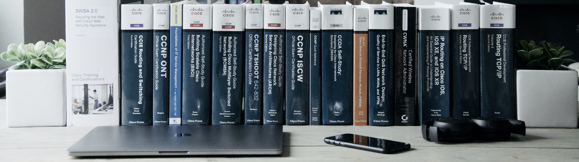
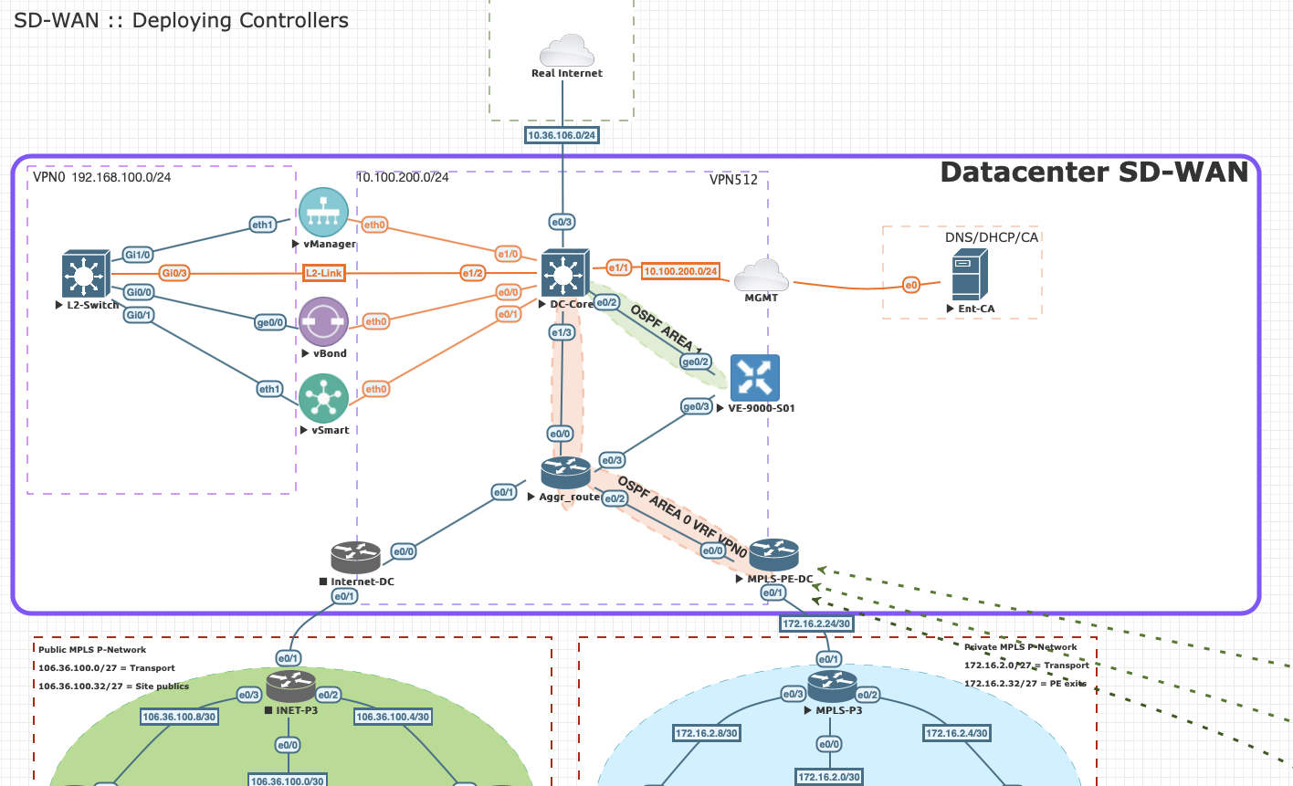
I’ve built my own on-prem lab:
One of the main prerequisites is that SD-WAN WAN Edges need IP reachability to the controllers. It doesn’t really matter how or via what protocol as this will remain the underlay and is invisible for the SD-WAN Fabric.
:: The problem
I started designing my topology in EVE-NG. I created a DC location and some remote sites. One of the traits is that a WAN Edge can replace the CPE device for MPLS or Internet and connect directly to a PE node. That’s not always the case. But let’s continue.
When installing the WAN-Edge I tried to tap into the OSPF configurations from DC-Core to get all the network routes and onboard the vEdge. Great that worked fine with manually building the configuration. OSPF neighbours are up and sharing IP routes with each other and we have ip reachability. But no onboarding happened.
The onboarding process requires the WAN Edge to be able to setup a TLS/DTLS tunnel to the controllers for onboarding.
With our OSPF configuration between DC-Core and VE-9000-S01 and a tunnel-interface on ge0/2 the following happened:
- OSPF neighbour with DC-Core went down
- Withdrawn of IP routes
- Lost reachability to controllers
By removing the Tunnel-interface command OSPF neigbours came back up and IP routes are shared again. Chicken and egg syndrome??
Ok, so either I can use traditional IP connectivity or a tunnel-interface and a lot of manual static routes.
:: Service side versus Transport side
his pushes us to think about how the WAN Edge is meant to be used.
The best way to think about it is to divide a WAN Edge into two parts:
- Services-side: Traditional configuration with OSPF or static to pass IP routes. No tunnel-interfaces
- Transport-side: The place where OMP magic happens. The transport side forms the overlay network and is based in IPsec tunnels. Also they setup a DTLS tunnel to the controllers back in the datacenter. Service-side IP routes are redistributed into OMP to pass over the fabric.
So when the controllers live on the On-Prem Datacenter the local WAN Edge cannot be positioned as a CPE device for MPLS or Internet directly.
:: How to solve it?
To solve this puzzle we just need to add an aggregated device to connect MPLS and Internet circuits to it.
The transport side will be connected to the Aggr_router and will provide tunnel capabilities towards the controllers. The Service side will be connected to the DC-Core.

But hold on for just one second! Basically the same setup!
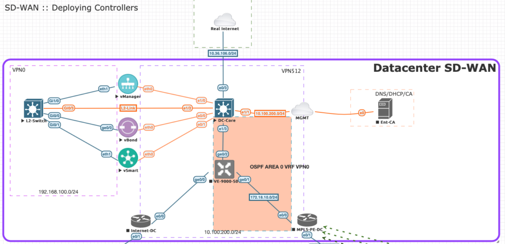
Not quite! On the Service side we’ve enable OSPF Area 1:
VE-9000-S01# show run vpn 1
vpn 1
 router
  ospf
   timers spf 200 1000 10000
   area 1
    interface ge0/2
    exit
   exit
  !
 !
 interface ge0/2
  ip address 10.10.10.5/30
  no shutdown
 !
!
VE-9000-S01# show ospf neighbor
DBsmL -> Database Summary List
RqstL -> Link State Request List
RXmtl -> Link State Retransmission List
       SOURCE                                                                    DEAD
VPN    IP ADDRESS       INTERFACE        ROUTER ID        STATE        PRIORITY  TIMER  DBsmL  RqstL  RXmtL
-------------------------------------------------------------------------------------------------------
1      10.10.10.6       ge0/2            9.9.9.9          full         1         36     0      0      0

VE-9000-S01# sh ip route vpn 1
Codes Proto-sub-type:
  IA -> ospf-intra-area, IE -> ospf-inter-area,
  E1 -> ospf-external1, E2 -> ospf-external2,
  N1 -> ospf-nssa-external1, N2 -> ospf-nssa-external2,
  e -> bgp-external, i -> bgp-internal
Codes Status flags:
  F -> fib, S -> selected, I -> inactive,
  B -> blackhole, R -> recursive, L -> import

                                            PROTOCOL  NEXTHOP     NEXTHOP          NEXTHOP
VPN    PREFIX              PROTOCOL         SUB TYPE  IF NAME     ADDR             VPN      TLOC IP          COLOR            ENCAP  STATUS
---------------------------------------------------------------------------------------------------------------------------------------------
1      0.0.0.0/0           ospf             E2        ge0/2       10.10.10.6       -        -                -                -      F,S
1      10.10.10.4/30       ospf             IA        ge0/2       -                -        -                -                -      -
1      10.10.10.4/30       connected        -         ge0/2       -                -        -                -                -      F,S
1      10.36.106.0/24      ospf             IA        ge0/2       10.10.10.6       -        -                -                -      F,S
The service side never tunnels back to controllers or other components. It will only make sure all DC routes are advertised in OMP later on.
For the transport side we’ve used to following static config:
VE-9000-S01# sh run vpn 0
vpn 0
 interface ge0/1
  ip address 172.18.10.2/24
  no shutdown
 !
 interface ge0/3
  ip address 10.10.10.10/30
  tunnel-interface
   encapsulation ipsec
   allow-service all
   no allow-service bgp
   allow-service dhcp
   allow-service dns
   allow-service icmp
   allow-service sshd
   allow-service netconf
   no allow-service ntp
   no allow-service ospf
   no allow-service stun
   allow-service https
  !
  no shutdown
 !
 ip route 0.0.0.0/0 10.10.10.9
!

VE-9000-S01# sh ip route vpn 0
Codes Proto-sub-type:
  IA -> ospf-intra-area, IE -> ospf-inter-area,
  E1 -> ospf-external1, E2 -> ospf-external2,
  N1 -> ospf-nssa-external1, N2 -> ospf-nssa-external2,
  e -> bgp-external, i -> bgp-internal
Codes Status flags:
  F -> fib, S -> selected, I -> inactive,
  B -> blackhole, R -> recursive, L -> import

                                            PROTOCOL  NEXTHOP     NEXTHOP          NEXTHOP
VPN    PREFIX              PROTOCOL         SUB TYPE  IF NAME     ADDR             VPN      TLOC IP          COLOR            ENCAP  STATUS
---------------------------------------------------------------------------------------------------------------------------------------------
0      0.0.0.0/0           static           -         ge0/3       10.10.10.9       -        -                -                -      F,S
0      4.1.1.1/32          connected        -         system      -                -        -                -                -      F,S
0      10.10.10.8/30       connected        -         ge0/3       -                -        -                -                -      F,S
Since we have a route (via default) towards our controllers (192.168.100.0/24) and a configured tunnel-interface a control tunnel can be setup towards the vBond, vSmart and vManage.
VE-9000-S01# show control connections
                                                                                       PEER                                          PEER                                          CONTROLLER
PEER    PEER PEER            SITE       DOMAIN PEER                                    PRIV  PEER                                    PUB                                           GROUP
TYPE    PROT SYSTEM IP       ID         ID     PRIVATE IP                              PORT  PUBLIC IP                               PORT  LOCAL COLOR     PROXY STATE UPTIME      ID
----------------------------------------------------------------------------------------------------------------------------------------------------------------------------------------
vsmart  dtls 1.1.1.3         9000       1      192.168.100.251                         12346 192.168.100.251                         12346 default         No    up     0:05:22:26  0
vbond   dtls 0.0.0.0         0          0      192.168.100.252                         12346 192.168.100.252                         12346 default         -     up     0:05:22:27  0
vmanage dtls 1.1.1.1         9000       0      192.168.100.250                         12546 192.168.100.250                         12546 default         No    up     0:04:37:38  0
:: Conclusion
You cannot replace the existing CPE with a WAN Edge when your controllers are behind that device in the datacenter. You must have an extra aggregation point so the “outside” interface of the WAN Edge can setup a tunnel towards the controllers on the “Inside”.
Some things you need to fail multiple times in before cracking the code of learning. And failure is your key to success.